I like learning by building programs that are useless but fun. Lately I’d been feeling my mental energy running low, and I wanted the kind of fun that refills it, like Jazzlang(Korean), which I built for fun last year. While looking around for something to do, I remembered a YouTube video I had watched around this time last year. In the video, someone quietly codes a program that spins a cube in the terminal, from start to finish.
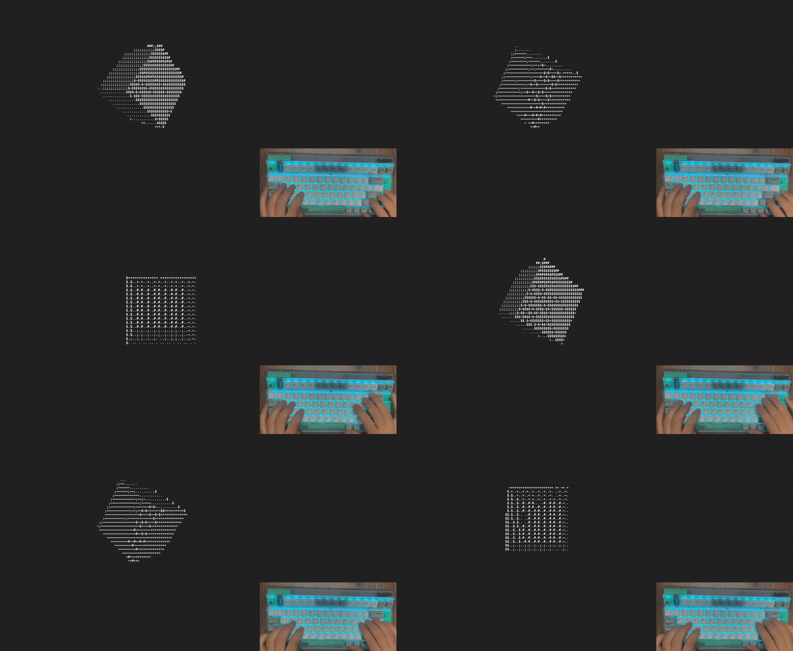
I thought it was a really fresh idea. I happened to be in the mood to build something, so I started wondering, if a cube works, couldn't other objects be rendered in 3D in the terminal too? Then I went ahead and built it. The finished renderer from this article is in the GitHub repository and on Chromatic.
How Do You Make ASCII Look 3D?
3D rendering covers some very difficult techniques, like light and shadow, optimization, shaders, collision handling, and physics. But since all we’re going to do is draw a 3D object on the screen, a few basic techniques are enough. Why do we perceive an object on a screen as sitting in three-dimensional space? The answer is simple. The screen expresses perspective. There are many ways to make a person feel perspective, but in an ordinary terminal the only ones available are lines1 and shading.
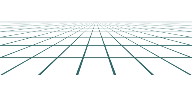
Expressing perspective with lines is simple. You use the fact that things far away eventually converge to a single point. In art this is called a vanishing point. There can be more than one.
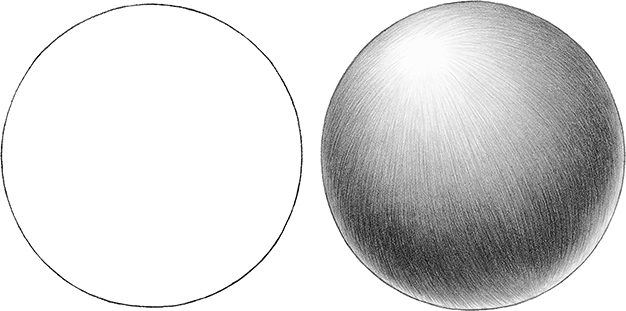
Expressing perspective with shading is even simpler. Draw it bright where there is light and dark where there is none. That gives the object a sense of solid form.
But can you express perspective and solidity with nothing but ASCII? To give the conclusion first, think of ASCII characters as slightly large pixels. Look at the image below.
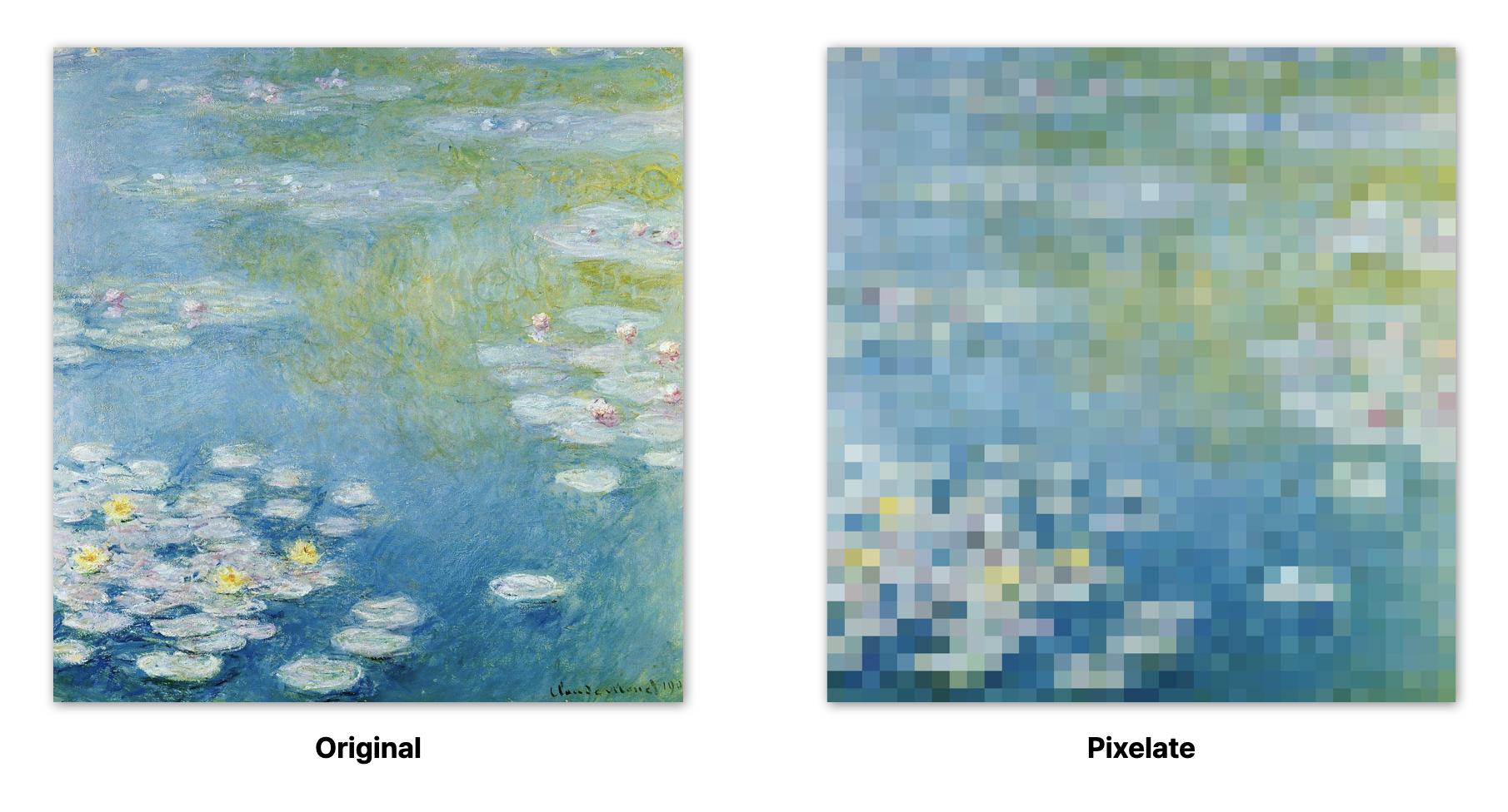
On the left is the original image, and on the right is the same image with a pixelate effect. Using ASCII is not much different from producing the image on the right, only with characters instead of pixels. There are artworks that use this idea.

The image above shows that text alone is enough to express an image. And since closer parts are drawn with denser characters and farther parts with lighter ones, assuming the light comes from the direction you are looking, it manages to express perspective and shading as well.
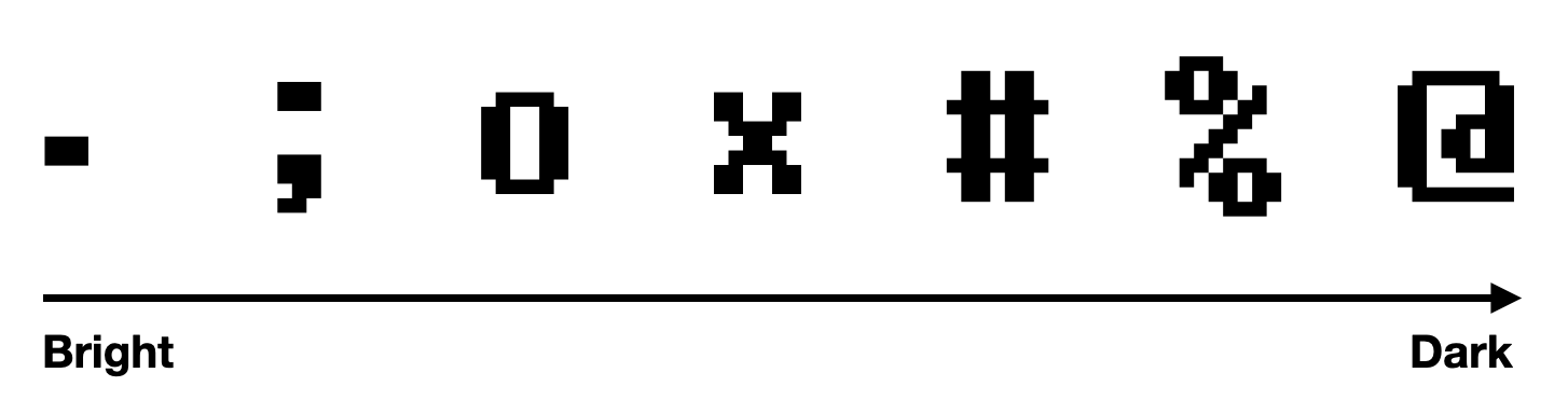
The spacing has to be uniform, so a monospaced font is a must. Shading done the way the cube in that YouTube video does it looks like this.
The example above is my own port of the program from the video, made to run in the browser. The shading isn’t based on a light source, but each face has a different shade, so you get a sense of solid form. Next, let’s go over what we need to know to build this.
From 3D Coordinates to 2D
The object we want to show exists in 3D space, but a monitor is a 2D surface. So to display it, we need to convert the 3D space defined by values into something visible on the 2D space of the screen. This conversion process is called the rendering pipeline.
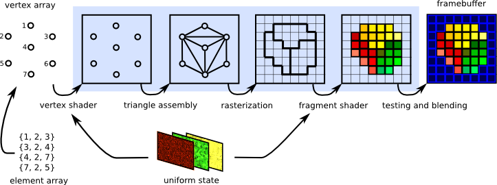
The goal of this article is only to draw a 3D object with ASCII, so we’ll implement just part of the rendering pipeline. For that reason I won’t explain the whole thing in detail, only the parts we need. Broadly, the rendering pipeline consists of three stages.
- Vertex processing
- Rasterization
- Fragment processing
Let’s look at each stage in turn.
Vertex Processing
To represent 3D space, you need 3D coordinates. 3D coordinates use the Cartesian coordinate system, expressing a position along three axes as (x, y, z). It sounds like a difficult term, but it just means describing a position with three values.
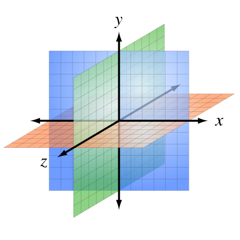
A coordinate expressed this way is called a vertex, meaning a point positioned in 3D space. A single vertex can’t represent an object, so vertices are gathered together to represent one. The smallest unit used to represent an object is called a polygon. Apart from special cases2, a polygon is usually a triangle made of three vertices. The reason it is a triangle is that a triangle is the smallest unit that can form a surface, and it is efficient.
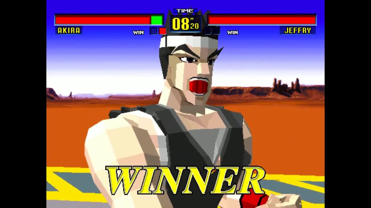
A single object made of vertices and polygons like this is called a polygon mesh. Usually a developer loads a 3D model file made by a designer and builds the polygon mesh from it. A 3D model file holds a variety of information, including the vertices and polygons, and that information is what lets us represent the object. The step in this process where vertices are transformed is called vertex processing.
Various things can be done to vertices in the vertex processing stage, but transformation is the most basic. The transformation here is the core of moving 3D space onto a 2D screen. In vertex processing, transformation usually goes through three steps.
- World transform
- View transform
- Projection transform
Each transform is handled with a matrix. Let’s look at each one.
World Transform
The world transform places the vertices held in the 3D model file into a 3D space called the world. The 3D model file has fixed values in its own space, but new values have to be assigned depending on where in the world it is placed, how large it is, and how it is rotated. Because it changes the model’s coordinates to place it in the world, it is also called the model transform.
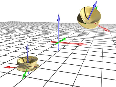
As mentioned earlier, coordinate transforms are handled with matrices. Even though we are dealing with three-dimensional coordinates, the matrix used for the transform is 4x4. If you only handled one of them at a time, a 3x3 matrix would do, but to handle translation, scale, and rotation all at once you need a 4x4 matrix.3
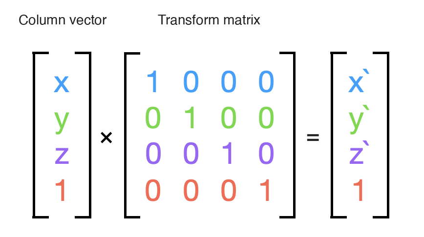
There are matrices for translation, scale, and rotation, but for now it’s enough to know that they exist. To put it briefly, multiplying the column vector for a vertex position (a 1×4 matrix) by each of these matrices is the world transform. Once the world transform is done, the loaded model has been placed in the world with absolute coordinates.
View Transform
The world transform placed the model in the world with absolute coordinates, but it still can’t be shown on the screen. To show it on the screen, we need to know from which position, and from which viewpoint, the object is being looked at. The thing that holds that position and viewpoint is called the camera, and how the object appears changes with the camera’s position. So we place the camera’s position and direction in the world and transform the model’s coordinates relative to the camera’s position. This is called the view transform. Since it depends on the camera’s values, it is also called the camera transform.
Three values describe a camera.
- Camera position (Eye)
- Camera direction (Look)
- Camera up vector (Up)
The position is where in the world the camera sits, the direction is which way it faces, and the up vector tells it which way is up. The up vector has to be perpendicular to the direction. These three values make up a coordinate system that describes the camera, called the camera coordinate system.
When the view transform runs, it uses the camera coordinate system to transform the coordinates of every other object relative to the camera. So you apply the inverse matrix of the camera to every object. The view transform does not yet express perspective, though. For perspective you need the projection transform.
Projection Transform
As mentioned above, the projection transform is what gives us perspective. Projection transforms divide broadly into orthographic and perspective projection, but orthographic projection doesn’t express perspective4, so 3D rendering uses perspective projection.
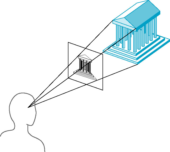
Perspective projection handles the transform through four properties.
- Field of view
- Aspect ratio
- Near plane
- Far plane
Field of view is how wide an angle the camera takes in, aspect ratio is the screen’s width relative to its height, and the near and far planes bound how much of the scene the camera can see. Perspective projection is computed from these four.
From these four properties you can build the projection matrix. The projection matrix is a 4x4 matrix, and it converts coordinates that have been through the view transform into 2D coordinates. We’ll see exactly how it’s built in the implementation below.
After the projection transform, the 3D coordinates have become 2D coordinates. Now rasterization has to turn those 2D coordinates into pixel coordinates.
Rasterization
Once vertex processing has turned 3D coordinates into 2D coordinates, turning those 2D coordinates into pixel coordinates is called rasterization. Rasterization usually goes through these steps.
- Clipping
- Perspective division
- Back-face culling
- Viewport transform
- Scan conversion
Clipping is cutting away polygons that lie outside the camera’s view after the projection transform. Clipping cuts down on unnecessary computation.
Perspective division is the step that converts to 2D coordinates after the projection transform. This is where sizes get scaled according to the depth of the object as seen from the camera, producing perspective. The x, y, and z coordinates are divided by the w value of the 4D coordinate obtained from the projection transform.
Back-face culling is removing the back faces of objects, which cannot be seen from the camera. Like clipping, this cuts down on unnecessary computation.
The viewport transform is converting 2D coordinates into pixel coordinates. In this article, the viewport transform converts 2D coordinates into coordinates that can be shown in the terminal.
Scan conversion is filling in the space between the coordinates after they have been converted to pixels.
Fragment Processing
Fragment processing handles the coordinates that rasterization has turned into pixels. A variety of things can be done here. For example:
- Lighting calculation
- Texture mapping
- Alpha blending
Since we’re rendering ASCII, we won’t do texture mapping, which expresses the surface material, or alpha blending, which adjusts transparency. All we need is the lighting calculation, to work out the shading.
The lighting calculation uses light and shadow to compute shading. To compute light and shadow, you need the light’s position and direction. The light’s position and direction make up a coordinate system that describes the light, called the light coordinate system. Like the camera coordinate system, it is a coordinate system expressing the light’s position and direction.
Implementation
Now that we’ve covered the basics of the rendering pipeline, let’s use them to implement a rendering pipeline that draws a 3D object with ASCII. The code is too long to fit in the article, so I’ll explain only the necessary parts and leave a link to the full code in the GitHub repository.
Since we’re drawing with nothing but ASCII in the terminal, there are a couple of constraints.
- Exact pixel coordinates can’t be used.
- Textures can’t be applied.
Even if we know the exact pixel coordinates, the terminal can’t show them, so they have to be converted into coordinates that can be expressed in a grid of characters. Here we’ll use a two-dimensional array. And since textures can’t be applied, we need to define in advance the characters that will be used to express shading. The implementation has to take both into account.
Groundwork
We’ll need math everywhere, so let’s build the objects for it first.
class Matrix44 { /* ... */ }
class Vector2 { /* ... */ }
class Vector3 { /* ... */ }
class Vector4 { /* ... */ }I won’t write out the detailed code here, but each class needs to implement the basic add, subtract, multiply, and divide operations, along with the rotation, scale, and translation transforms described above.
Building the Model Loader
The model loader’s job is to load a 3D model file and extract the vertices and polygons. Here we’ll implement it for the obj format.
o Cube
v -1.000000 1.000000 1.000000
v -1.000000 -1.000000 1.000000
v -1.000000 1.000000 -1.000000
v -1.000000 -1.000000 -1.000000
v 1.000000 1.000000 1.000000
v 1.000000 -1.000000 1.000000
v 1.000000 1.000000 -1.000000
v 1.000000 -1.000000 -1.000000
f 5 3 1
f 3 8 4
f 7 6 8
f 2 8 6
f 1 4 2
f 5 2 6
f 5 7 3
f 3 7 8
f 7 5 6
f 2 4 8
f 1 3 4
f 5 1 2
Most obj files look like the above. v marks a vertex, and f is a face element, the shape formed by connecting vertices. Let’s use this to build the model loader.
class Loader {
  static loadFromFile(file: File): Promise<Polygon[]> {
    /* ... */
  }

  static loadFromString(string: string): Polygon[] {
    return this.parseOBJ(string);
  }

  private static parseOBJ(data: string): Polygon[] {
    const lines = data.split("\n");

    const vertices: Vector3[] = [];
    const polygons: Polygon[] = [];

    for (const line of lines) {
      const parts = line.trim().split(" ");
      if (parts[0] === "v") {
        vertices.push(
          new Vector3(
            parseFloat(parts[1]),
            parseFloat(parts[2]),
            parseFloat(parts[3])
          )
        );
      } else if (parts[0] === "f") {
        polygons.push(
          new Polygon([
            vertices[parseInt(parts[1]) - 1],
            vertices[parseInt(parts[2]) - 1],
            vertices[parseInt(parts[3]) - 1],
          ])
        );
      }
    }

    return polygons;
  }
}The code above parses the contents of an obj file and extracts the vertices and polygons. Nothing here is hard. It just splits the string on whitespace and stores the values. The polygons are built from the vertex information that has already been collected.
Building the Renderer
On to the renderer. It is made up of the following logic.
- Decide the positions of the light source and the camera.
- Load a 3D model.
- Apply the world, view, and projection transforms to the model’s vertices.
- Rasterize into coordinates that can be shown in the terminal.
- Compute shading based on the position of the light source.
- Output ASCII characters according to the shading.
We haven’t implemented the light source or the camera yet, so let’s implement each transform first. The camera will come naturally along the way. First, the basic frame of the renderer.
export class ASCII3DRenderer {
  el: HTMLElement;
  width: number;
  height: number;
  frameBuffer: string[][];
  depthBuffer: number[][];

  private Shade = '.;ox%@';

  constructor(_el: HTMLElement, width: number, height: number) {
    this.el = _el;
    this.width = width;
    this.height = height;
    this.frameBuffer = new Array(height + 1).fill(null).map(() => new Array(width + 1).fill(' '));
    this.depthBuffer = new Array(height + 1).fill(null).map(() => new Array(width + 1).fill(255));
  }

  run() {
    // FPS logic
  }

  private render() {
    this.clearFrameBuffer();
    this.process();
    this.drawFrameBuffer();
  }

  private update() {
    // ...
  }

  private process() {
    // ...
  }

  private clearFrameBuffer() {
    // clear the buffers
  }

  private drawFrameBuffer() {
    // output to the screen
  }
}I called it a frame, but the code isn’t short. Each field in the class holds information needed for rendering. el is the element the rendering result is written to, width and height are the size of the result, frameBuffer is the space that holds the result, and depthBuffer is the depth buffer, which stores the depth of the result. Depth here means the distance from the camera.
Shade is the predefined string of characters used to express shading.
As for the methods, run keeps rendering at 60 frames per second, and render handles the rendering by clearing what was drawn and drawing the pipeline’s result. process performs the rendering pipeline work, such as vertex processing and rasterization. Once this part is filled in, the renderer is essentially complete. process will proceed like this.
- Decide the camera’s position and direction.
- Apply the world transform to the objects.
- Apply the view transform to the objects.
- Apply the projection transform to the objects.
- Rasterize into coordinates that can be shown in the terminal.
- Output ASCII characters according to the shading.
Setting Up Objects
Before implementing the camera, let’s first add an object for the renderer to render. An object can do the following.
- Load a polygon mesh from an
objfile. - Have its own rotation, position, and scale.
- Transform its vertices through matrix operations.
First, the object class.
export class Object {
  mesh: Polygon[];   // polygon mesh
  position: Vector3; // position
  rotate: Vector3;   // rotation
  scale: Vector3;    // scale

  constructor() {
    // initialize
    this.mesh = [];
    this.position = new Vector3(0, 0, 0);
    this.rotate = new Vector3(0, 0, 0);
    this.scale = new Vector3(1, 1, 1);
  }

  // load a polygon mesh from an obj file
  async loadFromFile(file: File) {
    this.mesh = await Loader.loadFromFile(file);
  }

  // load a polygon mesh from an obj string
  async loadFromString(string: string) {
    this.mesh = await Loader.loadFromString(string);
  }

  // a method for changing the object every frame
  update() {
    // override this method
  }

  // world transform
  transform(v: Vector4) {
    const matrix = Matrix44.identity()
      .multiply(Matrix44.rotateX(this.rotate.x))
      .multiply(Matrix44.rotateY(this.rotate.y))
      .multiply(Matrix44.rotateZ(this.rotate.z))
      .multiply(Matrix44.scale(this.scale))
      .multiply(Matrix44.translate(this.position));

    return v.transform(matrix);
  }

  /* Setter */

  setTranslate(v: Vector3) {
    this.position = v;
  }

  setScale(v: Vector3) {
    this.scale = v;
  }

  setRotateX(angle: number) {
    this.rotate.x = angle;
  }

  setRotateY(angle: number) {
    this.rotate.y = angle;
  }

  setRotateZ(angle: number) {
    this.rotate.z = angle;
  }
}This is the Object class. Object holds a polygon mesh in its mesh field and its position, rotation, and scale in the position, rotate, and scale fields. The loadFromFile and loadFromString methods load an obj file and set the polygon mesh, and the transform method transforms the vertices.
The matrix that transforms the vertices is the identity matrix multiplied by the rotation, scale, and translation transform matrices.
The update method is for changing the object every frame, and it’s meant to be overridden. The setTranslate, setScale, setRotateX, setRotateY, and setRotateZ methods set the position, scale, and rotation. As the update method suggests, the Object class is designed to be subclassed.
Next, modify the renderer so objects can be added to it.
export class ASCII3DRenderer {
  objects: Object[] = [];

  placeObject(object: Object) {
    this.objects.push(object);
  }

  // ...
}
That covers the basic object implementation and adding objects to the renderer. Next, vertex processing.
Vertex Processing
Vertex processing applies the world, view, and projection transforms to an object’s vertices. Let’s start by applying the world transform to the renderer’s objects.
export class ASCII3DRenderer {
  // ...

  private process() {
    for (const object of this.objects) {
      for (const polygon of object.mesh) {
        // convert to Vector4 for 4x4 matrix math
        let v1 = new Vector4(polygon.vertices[0].x, polygon.vertices[0].y, polygon.vertices[0].z, 1);
        let v2 = new Vector4(polygon.vertices[1].x, polygon.vertices[1].y, polygon.vertices[1].z, 1);
        let v3 = new Vector4(polygon.vertices[2].x, polygon.vertices[2].y, polygon.vertices[2].z, 1);

        // world transform
        v1 = object.transform(v1);
        v2 = object.transform(v2);
        v3 = object.transform(v3);

        // ...
      }
    }
  }
}
Since we need 4x4 matrix math, we walk the object’s polygons and convert each vertex into a 4D coordinate. Then object.transform applies the world transform to each vertex. The math functions are already implemented, so applying them is simple. Now the view transform. The view transform needs a camera first, so let’s build the Camera class.
export class Camera {
  eye: Vector3;       // camera position
  look: Vector3;      // direction the camera is facing
  up: Vector3;        // camera's up direction
  rotate: Vector3;    // camera rotation angles

  constructor() {
    // set the camera's initial position, direction, up direction, and rotation
    this.eye = new Vector3(0, 0, 0);
    this.look = new Vector3(0, 0, 1);
    this.up = new Vector3(0, 1, 0);
    this.rotate = new Vector3(0, 0, 0);  // rotation angles around the x, y, and z axes
  }

  transform(v: Vector4) {
    // compute the camera's forward, right, and up vectors
    const forward = this.look.subtract(this.eye).normalize();
    const newUp = forward.cross(this.up).normalize();
    const right = newUp.cross(forward);

    const matrix = new Matrix44(
      right.x, right.y, right.z, 0,
      newUp.x, newUp.y, newUp.z, 0,
      forward.x, forward.y, forward.z, 0,
      this.eye.x, this.eye.y, this.eye.z, 1
    );

    return v.transform(matrix);
  }
}The code above implements the Camera class with the fields eye, look, up, and rotate, which hold the camera’s position, direction, up vector, and rotation. The transform method applies the view transform. Looking at the implementation, it’s more involved than the world transform. Let’s take it piece by piece.
forward, newUp, and right, in that order, are the forward vector, right vector, and up vector, and each is used to express the camera’s direction and position.
- Forward vector: the difference between where the camera looks and where it sits, normalized. This is the camera’s forward direction, and it’s what gives objects their depth.
- Right vector: the cross product of the forward vector and the up vector, normalized. It points to the camera’s right, which is what left-right movement and rotation of objects are built on.
- Up vector: the cross product of the right vector and the forward vector, normalized. It points up from the camera and handles up-down movement.
Normalizing a vector means keeping its direction but making its length 1. The vectors obtained this way are used to build the view transform matrix, which is applied to the vertices. Time to add the camera to the renderer and apply the view transform.
export class ASCII3DRenderer {
  // ...

  camera: Camera = new Camera();

  private process() {
    this.camera.eye = new Vector3(0, 0, -3);

    for (const object of this.objects) {
      for (const polygon of object.mesh) {
        // convert to Vector4 for 4x4 matrix math
        let v1 = new Vector4(polygon.vertices[0].x, polygon.vertices[0].y, polygon.vertices[0].z, 1);
        let v2 = new Vector4(polygon.vertices[1].x, polygon.vertices[1].y, polygon.vertices[1].z, 1);
        let v3 = new Vector4(polygon.vertices[2].x, polygon.vertices[2].y, polygon.vertices[2].z, 1);

        // world transform
        v1 = object.transform(v1);
        v2 = object.transform(v2);
        v3 = object.transform(v3);

        // view transform
        v1 = this.camera.transform(v1);
        v2 = this.camera.transform(v2);
        v3 = this.camera.transform(v3);

        // ...
      }
    }
  }
}
Only the projection transform is left. Let’s build a Projection class to handle it.
export class Projection {
  fov: number;
  aspect: number;
  near: number;
  far: number;

  constructor(fov: number, aspect: number, near: number, far: number) {
    this.fov = fov;
    this.aspect = aspect;
    this.near = near;
    this.far = far;
  }

  transform(v: Vector4) {
    const fovRad = this.fov * (Math.PI / 180);
    const f = 1.0 / Math.tan(fovRad / 2);
    const rangeInv = 1.0 / (this.near - this.far);

    // prettier-ignore
    const matrix = new Matrix44(
      f / this.aspect, 0, 0, 0,
      0, f, 0, 0,
      0, 0, (this.near + this.far) * rangeInv, -1,
      0, 0, this.near * this.far * rangeInv * 2, 0
    );

    const transformed = v.transform(matrix);

    transformed.x /= transformed.w;
    transformed.y /= transformed.w;
    transformed.z /= transformed.w;

    return transformed;
  }
}
The Projection class has the fields fov, aspect, near, and far, which hold the field of view, aspect ratio, near plane, and far plane. The transform method applies the projection transform. The explanation of the formula is a bit involved, so I’ll skip it here. Then apply the projection transform in the renderer.
export class ASCII3DRenderer {
  // ...
  projection: Projection;

  constructor(_el: HTMLElement, width: number, height: number) {
    // ...
    this.projection = new Projection(70, width / 2 / height, 0.1, 100);
  }

  private process() {
    this.camera.eye = new Vector3(0, 0, -3);

    for (const object of this.objects) {
      for (const polygon of object.mesh) {
        // convert to Vector4 for 4x4 matrix math
        let v1 = new Vector4(polygon.vertices[0].x, polygon.vertices[0].y, polygon.vertices[0].z, 1);
        let v2 = new Vector4(polygon.vertices[1].x, polygon.vertices[1].y, polygon.vertices[1].z, 1);
        let v3 = new Vector4(polygon.vertices[2].x, polygon.vertices[2].y, polygon.vertices[2].z, 1);

        // world transform
        v1 = object.transform(v1);
        v2 = object.transform(v2);
        v3 = object.transform(v3);

        // view transform
        v1 = this.camera.transform(v1);
        v2 = this.camera.transform(v2);
        v3 = this.camera.transform(v3);

        // projection transform
        v1 = this.projection.transform(v1);
        v2 = this.projection.transform(v2);
        v3 = this.projection.transform(v3);
      }
    }
  }
}
If you’ve made it this far, vertex processing is done.
Rasterization
You may be getting bored, since we haven’t seen any output yet. Once rasterization is implemented, we’ll finally get to see real results. Before it gets any more tedious, let’s do something light and connect the three coordinates of each vertex with lines.
export class ASCII3DRenderer {
  private process() {
    this.camera.eye = new Vector3(0, 0, -3);

    for (const object of this.objects) {
      for (const polygon of object.mesh) {
        // ...

        // rasterization
        this.rasterize(v1, v2, v3);
      }
    }
  }

  private rasterize(v1: Vector4, v2: Vector4, v3: Vector4) {
    // convert the points to screen coordinates
    const p1 = new Vector2(((v1.x + 1) * this.width) / 2, ((1 - v1.y) * this.height) / 2);
    const p2 = new Vector2(((v2.x + 1) * this.width) / 2, ((1 - v2.y) * this.height) / 2);
    const p3 = new Vector2(((v3.x + 1) * this.width) / 2, ((1 - v3.y) * this.height) / 2);

    // draw the lines
    this.drawLine(p1, p2);
    this.drawLine(p2, p3);
    this.drawLine(p3, p1);
  }

  private drawLine(p1: Vector2, p2: Vector2) {
    const result = p2.subtract(p1);
    const len = result.length();
    const normalized = result.normalize();

    for (let i = 0; i < len; i++) {
      const current = normalized.multiply(i);
      const p = p1.add(current);

      // ignore coordinates that fall off the screen
      if (p.x >= 0 && p.x < this.width && p.y >= 0 && p.y < this.height) {
        this.frameBuffer[Math.floor(p.y)][Math.floor(p.x)] = '#';
      }
    }
  }
}
In the code above, the rasterize method converts the vertices to screen coordinates and draws lines with the drawLine method. drawLine finds the distance between two points and puts a ’#’ at each coordinate along the way. Now let’s add an object to the renderer and render it. Here I’ll create a Cube object and add that.
import { Vector3 } from '../math';
import { Object } from '../object';

export class Cube extends Object {
  angle = 0;

  constructor() {
    super();
    this.loadFromString(mesh);
  }

  override update(): void {
    this.setRotateX(-this.angle * 2);
    this.setRotateY(-this.angle * 2);
    this.setRotateZ(-this.angle);
    this.setTranslate(new Vector3(0, 0, -5));
    this.angle += 0.007;
  }
}

export const mesh = /* contents of the obj file */;
As you can see, angle rotates the object a little every frame. Add it to the renderer and render. The code doesn’t have to look exactly like this.
const renderer = new ASCII3DRenderer(document.getElementById('app'), 150, 50);
const cube = new Cube();
renderer.placeObject(cube);
renderer.run();
With this in place you can see the rendering result in the browser. Let’s take a look.

It’s a little awkward, but it does look like a cube rotating. This time, let’s fill in the space between the vertices.
export class ASCII3DRenderer {
  private process() {
    this.camera.eye = new Vector3(0, 0, -3);

    for (const object of this.objects) {
      for (const polygon of object.mesh) {
        // ...

        // rasterization
        this.rasterize(v1, v2, v3);
      }
    }
  }

  private rasterize(v1: Vector4, v2: Vector4, v3: Vector4) {
    // convert the points to screen coordinates
    const p1 = new Vector2(((v1.x + 1) * this.width) / 2, ((1 - v1.y) * this.height) / 2);
    const p2 = new Vector2(((v2.x + 1) * this.width) / 2, ((1 - v2.y) * this.height) / 2);
    const p3 = new Vector2(((v3.x + 1) * this.width) / 2, ((1 - v3.y) * this.height) / 2);

    // compute the triangle's bounding box
    const minX = Math.floor(Math.max(0, Math.min(p1.x, p2.x, p3.x)));
    const minY = Math.floor(Math.max(0, Math.min(p1.y, p2.y, p3.y)));
    const maxX = Math.floor(Math.min(this.width, Math.max(p1.x, p2.x, p3.x)));
    const maxY = Math.floor(Math.min(this.height, Math.max(p1.y, p2.y, p3.y)));

    for (let x = minX; x <= maxX; x++) {
      for (let y = minY; y <= maxY; y++) {
        const p = new Vector2(x, y);

        // if the point is inside the triangle
        if (this.isPointInTriangle(p, p1, p2, p3)) {
          this.setPixel(x, y);
        }
      }
    }
  }

  private isPointInTriangle(p: Vector2, p1: Vector2, p2: Vector2, p3: Vector2): boolean {
    // compute the sign of the three sub-triangles
    const b1 = this.sign(p, p1, p2) < 0;
    const b2 = this.sign(p, p2, p3) < 0;
    const b3 = this.sign(p, p3, p1) < 0;

    // if all sub-triangles have the same sign, the point is inside the triangle
    return b1 === b2 && b2 === b3;
  }

  // ...
}
Now the inside of each triangle is filled in too, and the drawLine method is no longer used. A cube without shading looks awkward, so I rendered a cow object instead.
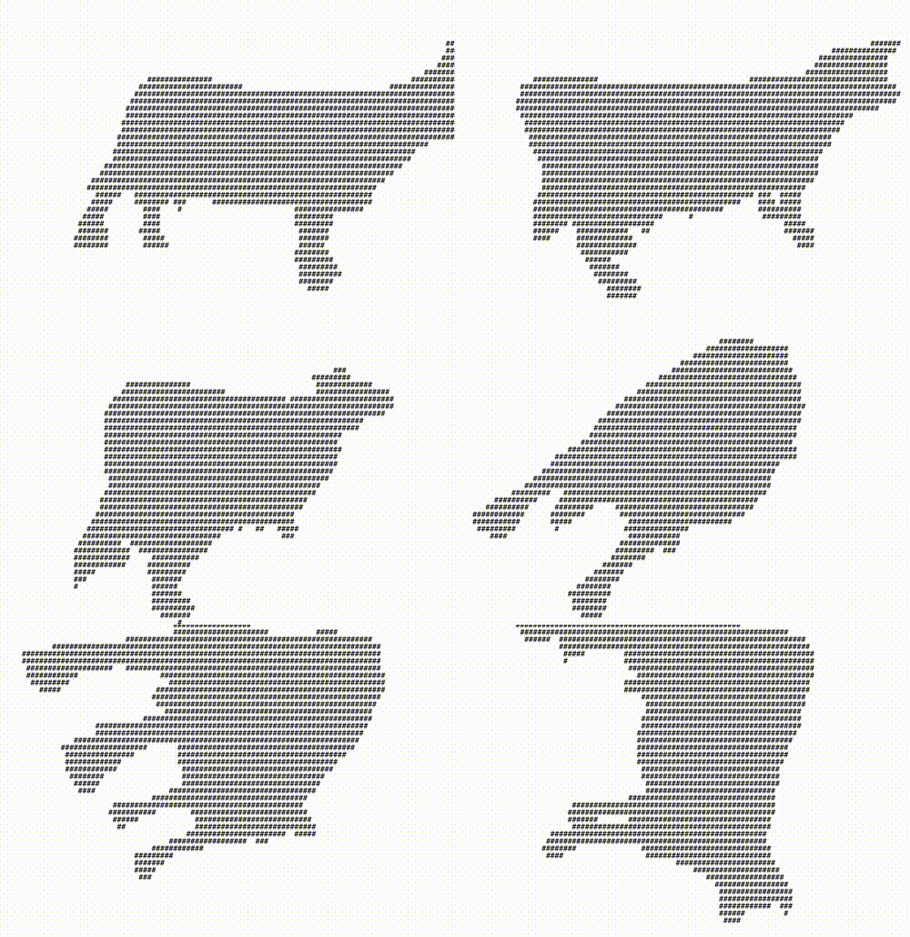
Lighting
Finally, let’s add shading. For that we need to add a light source.
export class ASCII3DRenderer {
  // ...

  private process() {
    this.camera.eye = new Vector3(0, 0, -2);

    for (const object of this.objects) {
      for (const polygon of object.mesh) {
        // convert to Vector4 for 4x4 matrix math
        let v1 = new Vector4(polygon.vertices[0].x, polygon.vertices[0].y, polygon.vertices[0].z, 1);
        let v2 = new Vector4(polygon.vertices[1].x, polygon.vertices[1].y, polygon.vertices[1].z, 1);
        let v3 = new Vector4(polygon.vertices[2].x, polygon.vertices[2].y, polygon.vertices[2].z, 1);

        // world transform
        v1 = object.transform(v1);
        v2 = object.transform(v2);
        v3 = object.transform(v3);

        // view transform
        v1 = this.camera.transform(v1);
        v2 = this.camera.transform(v2);
        v3 = this.camera.transform(v3);

        // lighting
        const brightness = this.calculateLight(v1, v2, v3);

        // projection transform
        v1 = this.projection.transform(v1);
        v2 = this.projection.transform(v2);
        v3 = this.projection.transform(v3);

        // rasterization
        this.rasterize(v1, v2, v3, brightness);
      }
    }
  }

  private calculateLight(v1: Vector4, v2: Vector4, v3: Vector4): number {
    // direction vector of the light source
    // uses the direction the camera is facing, (0, 0, 1)
    const lightDirection = new Vector3(0, 0, 1).normalize();

    // compute the triangle's surface normal
    const normal = this.calculateSurfaceNormal(
      new Vector3(v1.x, v1.y, v1.z),
      new Vector3(v2.x, v2.y, v2.z),
      new Vector3(v3.x, v3.y, v3.z)
    );

    // compute the angle between the light and the surface normal
    const cosAngle = normal.dot(lightDirection);

    // decide the pixel's brightness from the angle of the light
    const brightness = Math.max(0, cosAngle);

    return brightness;
  }

  private calculateSurfaceNormal(v1: Vector3, v2: Vector3, v3: Vector3): Vector3 {
    // define two edges
    const edge1 = v3.subtract(v2);
    const edge2 = v1.subtract(v3);

    // compute the cross product and return the surface normal
    return edge1.cross(edge2).normalize();
  }

  // ...
}
The lighting calculation has to happen between the view transform and the projection transform. After the projection transform, the coordinates have already become 2D, so it has to be done before that. In the code above, the calculateLight method uses the light’s direction vector and the triangle’s surface normal to compute the angle between them. A normal vector is a vector that represents the direction a plane is facing. The angle of the light against it decides the brightness of the pixel.
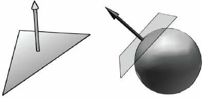
Now let’s output ASCII characters according to the shading.
export class ASCII3DRenderer {
  // ...

  private process() {
    this.camera.eye = new Vector3(0, 0, -2);

    for (const object of this.objects) {
      for (const polygon of object.mesh) {
        // convert to Vector4 for 4x4 matrix math
        let v1 = new Vector4(polygon.vertices[0].x, polygon.vertices[0].y, polygon.vertices[0].z, 1);
        let v2 = new Vector4(polygon.vertices[1].x, polygon.vertices[1].y, polygon.vertices[1].z, 1);
        let v3 = new Vector4(polygon.vertices[2].x, polygon.vertices[2].y, polygon.vertices[2].z, 1);

        // world transform
        v1 = object.transform(v1);
        v2 = object.transform(v2);
        v3 = object.transform(v3);

        // view transform
        v1 = this.camera.transform(v1);
        v2 = this.camera.transform(v2);
        v3 = this.camera.transform(v3);

        // lighting
        const brightness = this.calculateLight(v1, v2, v3);

        // projection transform
        v1 = this.projection.transform(v1);
        v2 = this.projection.transform(v2);
        v3 = this.projection.transform(v3);

        // rasterization
        this.rasterize(v1, v2, v3, brightness);
      }
    }
  }

  private rasterize(v1: Vector4, v2: Vector4, v3: Vector4, brightness: number) {
    // convert the points to screen coordinates
    const p1 = new Vector2(((v1.x + 1) * this.width) / 2, ((1 - v1.y) * this.height) / 2);
    const p2 = new Vector2(((v2.x + 1) * this.width) / 2, ((1 - v2.y) * this.height) / 2);
    const p3 = new Vector2(((v3.x + 1) * this.width) / 2, ((1 - v3.y) * this.height) / 2);

    // compute the triangle's bounding box
    const minX = Math.floor(Math.max(0, Math.min(p1.x, p2.x, p3.x)));
    const minY = Math.floor(Math.max(0, Math.min(p1.y, p2.y, p3.y)));
    const maxX = Math.floor(Math.min(this.width, Math.max(p1.x, p2.x, p3.x)));
    const maxY = Math.floor(Math.min(this.height, Math.max(p1.y, p2.y, p3.y)));

    // walk the inside of the box
    for (let y = minY; y <= maxY; y++) {
      for (let x = minX; x <= maxX; x++) {
        // ignore anything off the screen
        if (x < 0 || x >= this.width || y < 0 || y >= this.height) {
          continue;
        }

        const p = new Vector2(x, y);

        // if the point is inside the triangle
        if (this.isPointInTriangle(p, p1, p2, p3)) {
          // overwrite if the depth is lower
          if ((v1.w + v2.w + v3.w) / 3.0 <= this.depthBuffer[y][x]) {
            const shade = this.Shade[Math.round(brightness * (this.Shade.length - 1))];
            this.frameBuffer[y][x] = shade;
            this.depthBuffer[y][x] = (v1.w + v2.w + v3.w) / 3.0;
          }
        }
      }
    }
  }

  // ...
}
The shading picks a level from Shade according to the brightness value. depthBuffer also makes its first appearance here. The depth buffer stores the depth of each pixel drawn on the screen, and a pixel with a lower depth is closer to the front. It keeps pixels that are behind from overwriting pixels that are in front.
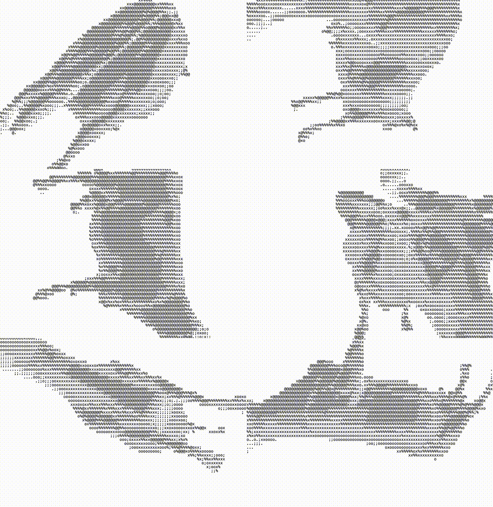
Using Extended ASCII
At this point it’s done. With a small change we can make the shading contrast more strongly, using extended ASCII.
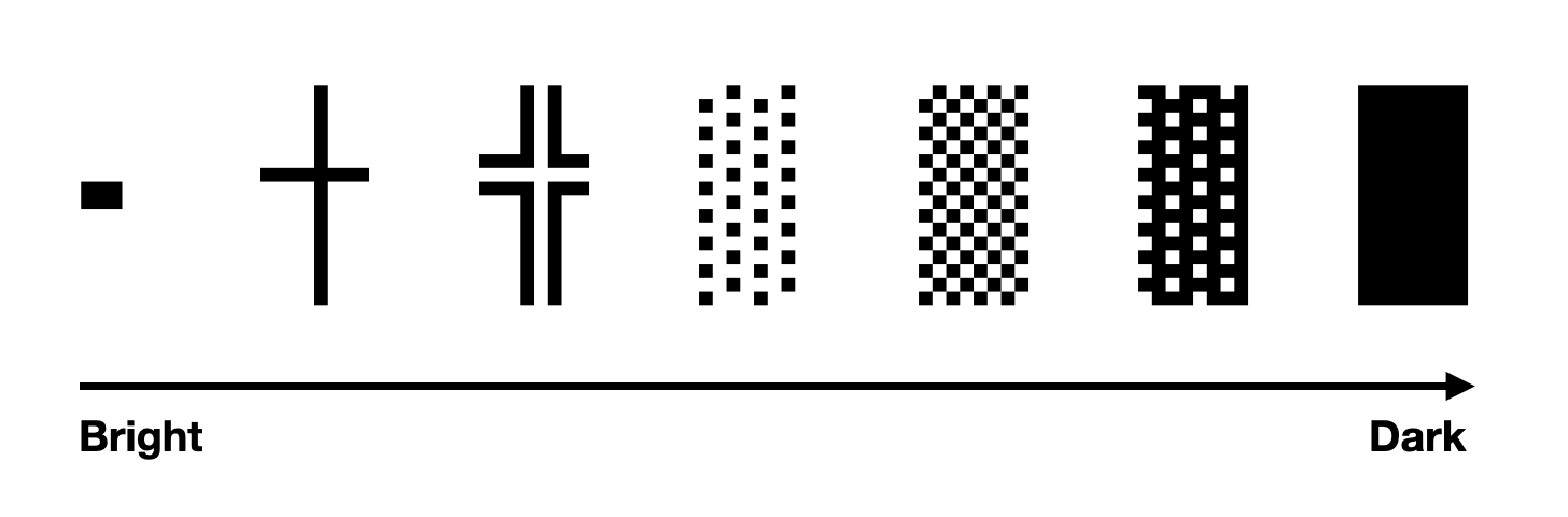
Nothing to it. Just change the Shade array.
private Shade = '·┼╬░▒▓█';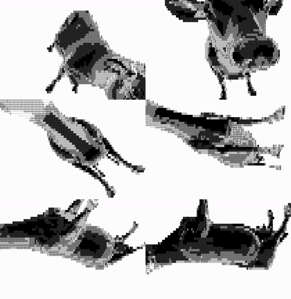
Closing
Since it’s implemented in JavaScript (built from TypeScript), it runs in the browser. The result can be seen on the web like this.
There are more examples on the separately deployed Chromatic page.
I started this project half for fun, but the implementation wasn’t as easy as I expected. I became a developer because I wanted to make games, but it has already been ten years since I last studied anything related to game development. Even so, working on this after such a long time was fun, and it felt like my brain was waking up again. It reminded me once more that learning comes down to trying things you don’t usually do and repeating them until they become familiar. If I get the chance, I’d like to do another fun project like this.
-
Strictly speaking, they aren’t lines. Just as small squares called pixels come together to look like a line, ASCII characters come together to look like one. ↩
-
3D modeling tools offer quad polygons for convenience while working. These are converted to triangles in post-processing. ↩
-
This is because of homogeneous coordinates. A homogeneous coordinate system extends 3D coordinates to 4D by adding a directional component, which lets rotation, translation, and scaling of 3D coordinates be handled in a single operation. ↩
-
For that reason it is commonly used for UI that needs to sit flat against the screen. ↩